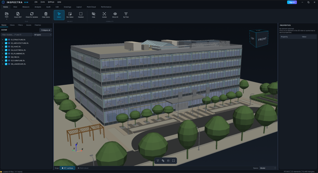
Inspectra BIM 0.10.0 — annotative drawings, DXF layer mapping and representation setups
Inspectra BIM 0.10.0 is out. This release is all about drawing production: annotations that finally behave the way CAD users expect, DXF exports that follow your office layer standard, and representation control you can save, reuse and share with your team. Here is what changed since 0.9.2.
Annotations are now fully annotative (Edit)
Every annotation — free text, labels and dimensions — is now sized in millimetres of paper times the drawing scale, exactly like annotative text in CAD. A 2.5 mm style on a 1:100 section means 0.25 m in the model, on screen, on the layout and in the exported DXF. No more pixel-glued captions drifting against the geometry as you zoom.
Each drawing carries its own Annotation Scale: you pick it right in the section dialog when creating the view, and you can change it later from Manage Drawings, the right-click menu or the properties panel — the open drawing updates immediately.
New tool: Annotation Area. Draw a rectangle over a part of the drawing and give it its own scale — every annotation anchored inside adopts that scale automatically. Perfect for detail regions that will be printed at a different scale than the rest of the sheet. When you place a drawing on a layout, the scale prompt now suggests the scales actually used by that drawing first.
A proper text editor (Edit)
Placing or double-clicking a text opens a new CAD-style Text Editor: pick a text style, then override anything locally — font, height in millimetres, bold/italic/underline, colour, rotation, and line justification for multi-line text. A symbols menu inserts Ø, °, ± and friends, and the edit box previews the final look live.
Annotation styles got a real hierarchy to match: shared Text Styles are now referenced by Label styles and Dimension styles instead of each defining its own font — one place to change typography for the whole standard.
Representation rules, rebuilt (Edit)
Representation Rules now give you full control from a single rule. Each rule expands into a panel where the Cut, Visible and Hidden line bands get their own colour, width, line type and visibility — or tick “one style for all line bands” for the classic behaviour. A separate switch turns the cut fill (hatch) off while keeping the outline. Per band, the top rule that actually sets it wins, and untouched bands fall through to the rules below — so one filter can silence the hidden lines and paint the visible ones yellow at the same time.
On top of that come Representation Setups: save the current rules as a named setup stored in the scene file, then load it onto any other drawing of that scene in two clicks. Setups export to a JSON file — one or several at once — so an office can keep a single representation standard and pass it between users and projects.
Representation Rules and DXF References also moved out of the Setup drop-down and are now standalone tiles on the Drawings tab — the tools you touch most are one click away.
DXF export that follows your office standard (Edit)
The DXF exporter learned three big things:
- Layer mapping. A plain-text mapping file assigns exported geometry to your company layers based on element attributes (property sets), with wildcard matching that ignores case and Polish diacritics. Each layer gets its colour (ACI or RGB), line type, line-type scale and lineweight; cut, visible and hidden edges can land on separate layers, as can hatches, terrain, texts, dimensions and labels. A built-in “Check file” validates the mapping before export, and an optional log file documents exactly how elements were mapped.
- Leaner files. Line simplification (Ramer–Douglas–Peucker) now cleans up exported geometry. The default mode is lossless — it only removes vertices that are perfectly collinear, so the geometry stays mathematically identical — and an optional tolerance in millimetres shrinks files further when you allow it. Connected segments are chained into polylines instead of thousands of loose lines. Dimension values are measured before export and never change.
- True WYSIWYG. The exporter now respects Representation Rules and manually hidden elements — what you see on the drawing is exactly what lands in the DXF.
Long sections, smoother (Edit)
The long-section dialog now asks for the viewing side — Right side (the convention: standing along increasing chainage, looking right) or Left side — instead of an abstract mirror checkbox. From/To stations and the view depth are editable directly in Manage Drawings (K+MMM station format, validated), and the open drawing re-renders the moment you commit a value. Picking an alignment or a placement point now shows a crosshair cursor with a status hint, so you always know the tool is waiting for you.
For every tier
- UI Scale in Settings (100–200%) — scale the whole interface for high-DPI monitors or just easier reading; applies after a restart.
- File → New (Ctrl+N) — start a fresh scene with a proper save prompt for unsaved work; Clear Scene stays as the instant, no-questions variant.
- Fixes: scenes containing only a mesh or a point cloud restore their saved view correctly on reopen; long sections keep their alignment axis after a scene is reopened; the chainage-labels toggle no longer parks in the corner of the screen; licences with the Edit module alone can now save scene files (previously saving required Audit).
Get Inspectra BIM 0.10.0
Download the installer from inspectrabim.com — the update installs over your existing version and keeps your licence and settings. If you already run Inspectra BIM, the app will let you know an update is available, or use Home → Check for Updates.
The drawing features described above are part of the Inspectra Edit module; the viewer, UI scaling and scene handling improvements are available in every tier, including the free one.
Wypróbuj na własnym modelu
Inspectra BIM Free otwiera IFC, E57/LAS i XML lokalnie — bez wtyczek, bez chmury.